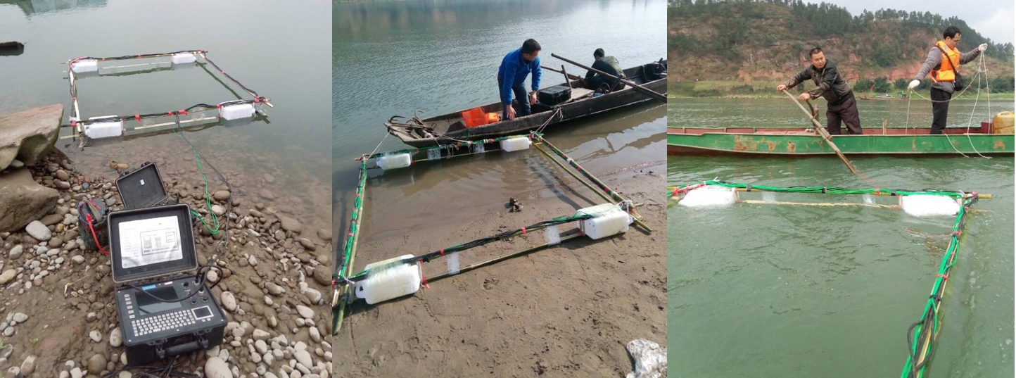
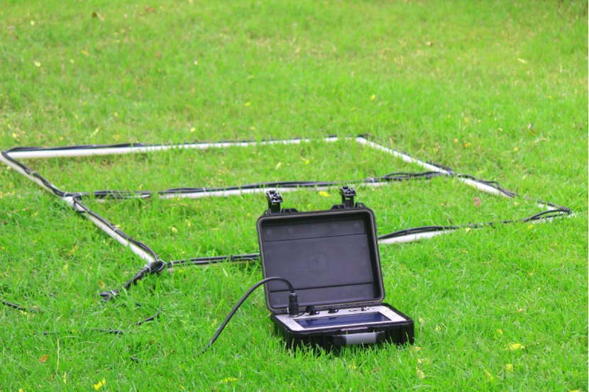
The LTEM 18 model High-Power Transient Electromagnetic instrument can currently emit pulse currents with an effective value of up to 100A. By increasing the transmission power, the secondary field is enhanced, which improves the signal-to-noise ratio (SNR) and thus increases the exploration depth. The use of repeated measurements and superposition of the secondary field excited by multiple pulses, along with the application of spatial domain multiple coverage techniques, also enhances the SNR. It is capable of being employed in complex working environments with significant noise interference, such as underground mines, tunnel tops, bottom plates, and advanced detection areas. This model features an integrated design of the receiver and transmitter, abandoning the traditional high-power transmitter to reduce the labor intensity of technical personnel at complex construction sites and improve work efficiency. The non-contact transmission and reception coils are integrated into a compact structure, making the system lightweight, easily transportable, and convenient to operate.
Applications
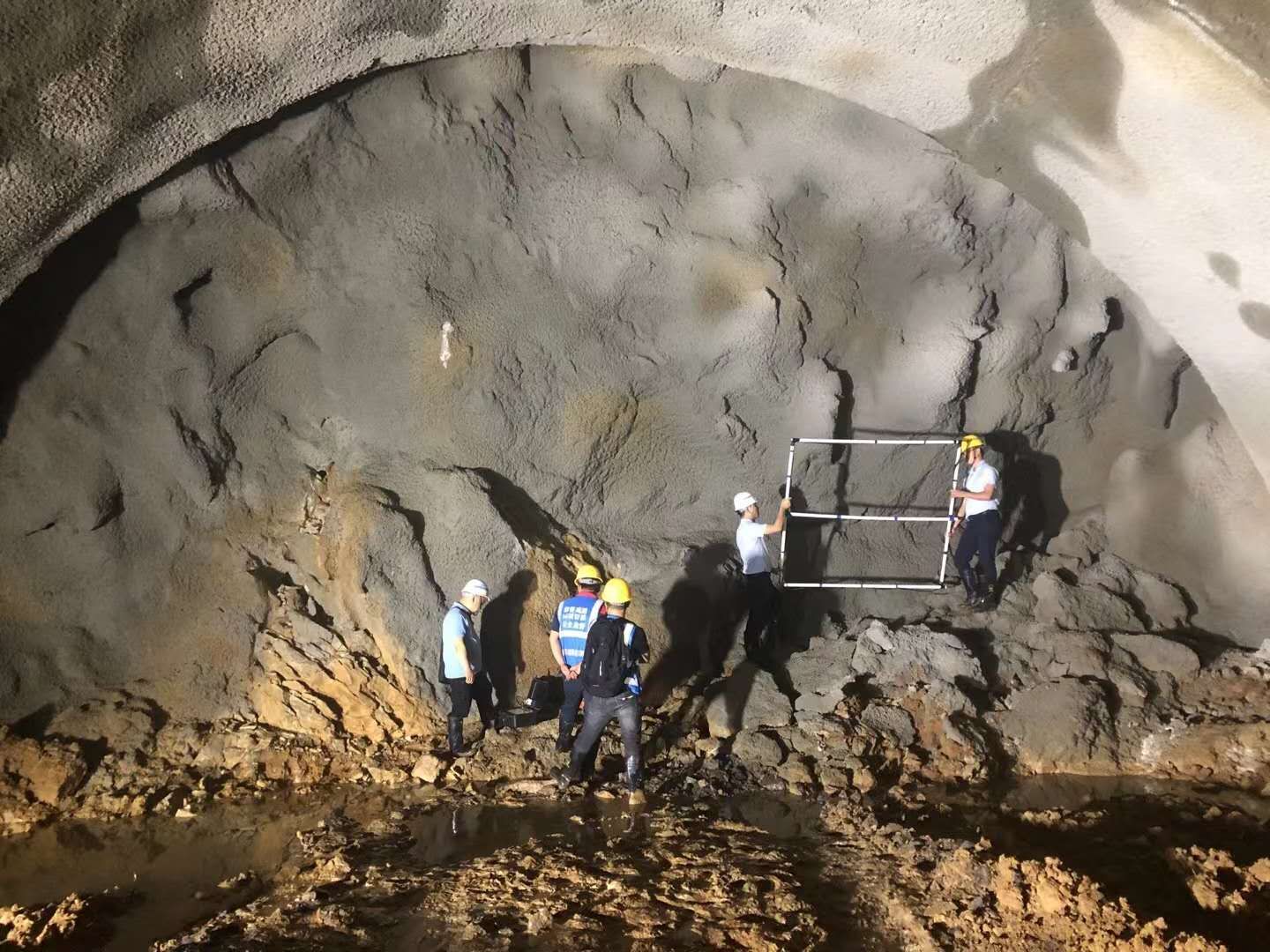
Advanced detection in tunnels, with an effective detection distance of more than 150 meters.
Exploration of geological structures around tunnels and galleries, detecting the structure distribution and water content of mines from the surface downwards.
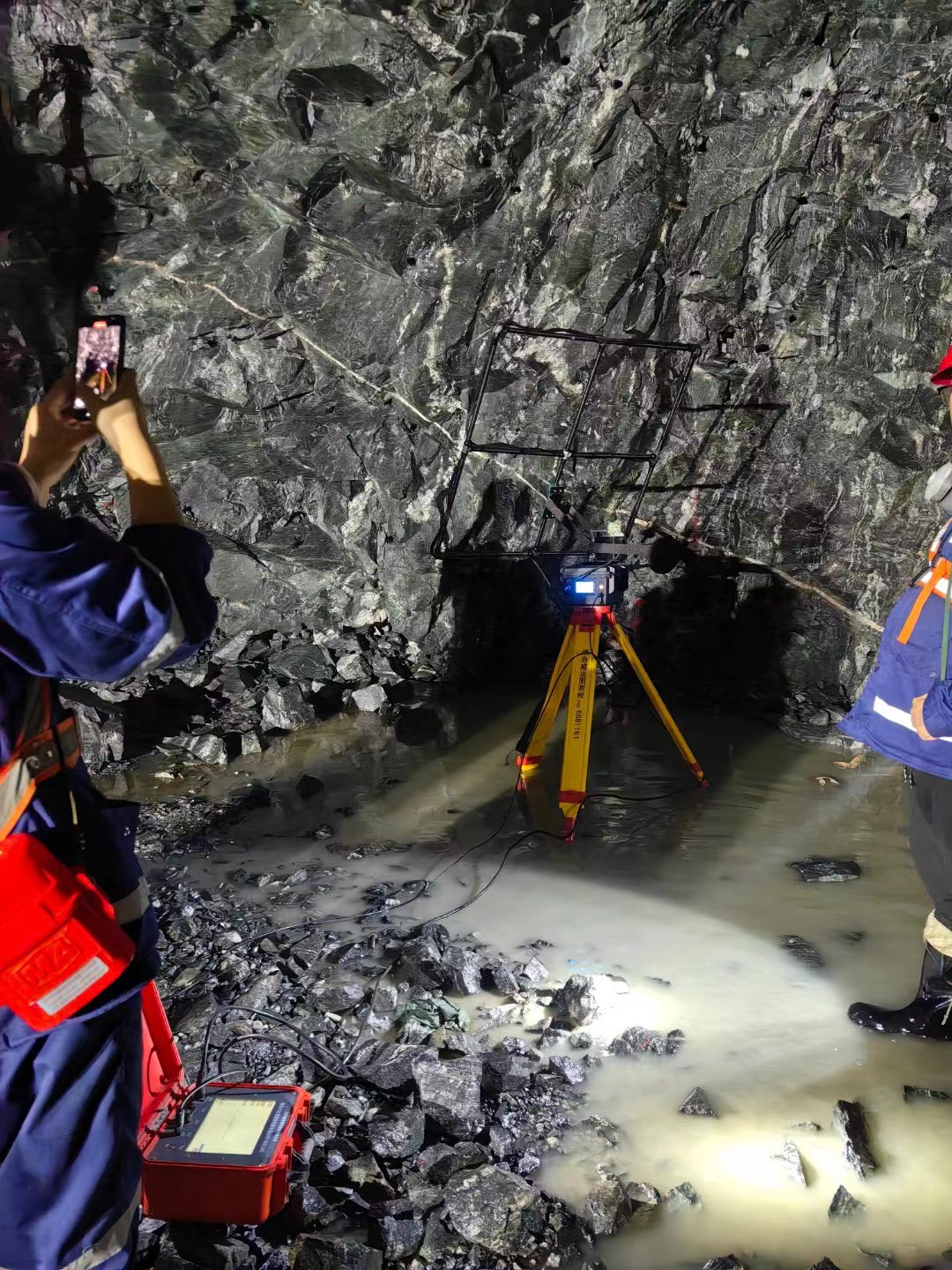
Investigation of hidden water-conducting structures during excavation.
Detection of well-conductive ore bodies, their burial depth, and ore-bearing structures, along with other engineering and environmental explorations.
Detection of the direction of ore veins in underground metal mines.
Detection of structures around underground caverns, metal pipelines detection.
Investigation of water sources in goaf areas and abandoned small coal mines, as well as sinkhole columns and other explorations.
Specifications
Transmitting Current Intensity | 100A |
Current Pulse Width | 1ms, 2ms, 3ms, 4ms, 5ms |
Current Emission Frequency | 256Hz, 75Hz, 62.5Hz, 12.5Hz, 6.25Hz, 1.5625Hz, lower; Unmodulated single rectangular pulse output, frequency error ±2% |
Coil Specifications | 1m*1m to 5m*5m (customizable by the user) |
Power Output Voltage | 16.8±0.2V |
Number of Stacks | Unlimited, optional; |
Shutdown Time | 0.1-20uS (related to coil inductance) |
Emission Waveform | Bipolar rectangular wave |
Main Control Unit | Military-grade low-power embedded system |
Number of Channels | Up to 1024 channels (user-definable) |
A/D Converter | 24 bit |
Minimum Sampling Interval | 1μS |
Dynamic Range | 140 dB |
Background Noise | 0.1uV |
Port | USB2.0 |
Memory | 2GB |
Data Storage | 16GB |
Display | TFT 10.4 inches (1024*800) 32-bit true color screen, LED backlight |
Hardware Platform | Embedded ARM processor Cortex-A8 |
Touch Screen | 10.4-inch high-precision touch screen |
Interpretation Software | Intelligent data processing and interpretation, one-click automatic mapping system, capable of matching and achieving 3D imaging display technology |
Power Supply | Built-in high-performance rechargeable battery |
Continuous Working Time | Over 10 hours |
Main Unit Dimensions | 406x330x174 (mm) (Length × Width × Height) |
Main Unit Weight | About 3.5Kg |
Operating Temperature | -20℃ to +40℃ |
Cases
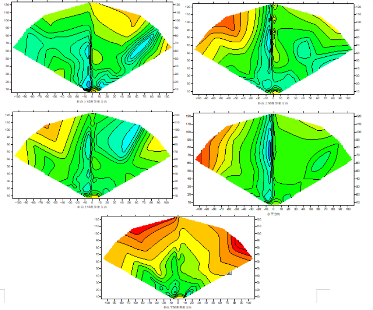
In a certain mine gallery, a detection of water-richness was conducted in the area 120 meters around the heading face and along the layer, aiming to analyze potential geological conditions such as fault structures.
Three-dimensional imaging shows that from directly ahead of the roof to along the layer, and in the direction slightly to the left by 0-15 degrees from the front, there are low-resistance areas within the 10~30m range and the 50~100m range from the working face, as indicated by the light blue areas in the figure. This anomaly is distributed from top to bottom, showing a certain degree of coherence and connectivity, with an overall apparent water-richness. Combining with the actual geological conditions, it is inferred that the anomaly might be a fault that extends from the top down. Based on this prediction, the mine conducted drilling in this direction, and three groups of boreholes produced water at close range, which was then drained and treated. The prediction was effective.
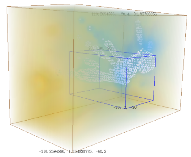
3D Diagram
Inclined Shaft Granite Driveway Advanced Forecasting
Conducting transient electromagnetic method advanced exploration at the 873 meter point of the inclined shaft to determine the location of the front fracture water-rich area with dense water content.
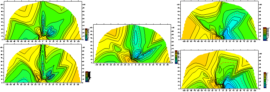
Advanced Exploration Results of 5 Profiles
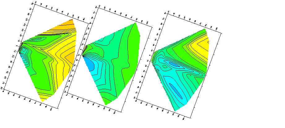
Longitudinal Detection Maps of Three Profiles: 30 Degrees to the Left, Directly Ahead, and 30 Degrees to the Right
Transient electromagnetic detection focuses on the layer-parallel direction (leaning downward at 20 degrees) for central analysis. The overall low-resistance area is distributed directly ahead and to the right of the front within a 0-60 degree area, with a distinct low-resistance anomaly observed within 10-50 meters directly ahead. From the roof downward, the resistivity and range of the low-resistance anomaly area gradually increase, suggesting a possible water-rich area ahead, mainly directly ahead and slightly to the right (as specifically indicated by the red dashed line on the map).
From a comprehensive analysis of both longitudinal and transverse profiles, the water-rich area ahead is primarily located in the layer-parallel direction and downward towards the bottom plate in the same direction. Altogether, it can be inferred that within a 10-50 meter range directly ahead and to the right by 60 degrees, primarily in the layer-parallel direction and downward towards the 60-degree bottom plate area, constitutes the main water-rich area. It is recommended that the mine focuses on drilling verification and subsequent treatment in this direction.